Wednesday, 18 December 2013

Off-grid living - Power system - Introduction

We have been living off-grid since 2006.
Our solar power generation system has been a great success.
I will be explaining certain parts of the PV system in the next series of posts.

First an overview of the PV system and its upgrades:
======================================================
The system as installed in December 2006 consisted of:
  • 1500W of Photovoltaic panels  
    • 12 PV panels  Sharp 123W Poly-crystalline
  • Outback Power Components 
    • FX3024E Inverter 3kW@240VAC
    • MX60 MPPT Charge Controller 60A@24V
    • MATE system controller
    • HUB4 system communication hub
    • Battery temperature monitor
  • Lead Acid Battery Bank 
    • Exide Energystore 24V (12x 2V cells) 1500Ahr @ C100
    • FLA (flooded lead acid) batteries
    • MegaPulse pulse generator for desulfation
  • Backup Power Generation
    • Generator to charge battery bank 
      • via FX3024E Inverter/Charger
      • while charging, generator supplies house 240V
    • 3kVA 240VAC 'silent' diesel generator
      • retired July 2007
    • Honda Eu20i generator 240VAC
      • added July 2007
  •   Switch boxes and breakers, fuses
    • PV panel circuit breakers at ~80V DC
    • MX 60 output breakers (both + and - sides)
    • Output 24V DC breaker (both + and - sides)
    • 24V DC heavy interconnection cabling
    • 240V AC fuse box
======================================================
The system was upgraded in December 2009:
  • Increase number of PV panels 
    • requirement run a 2.5kW reverse cycle air conditioner 
    • Extra PV requires a new, larger charge controller
  • Total 2000W of solar power 
    • Add 4 more 123W Sharp Photovoltaic panels
    • Total 16 panels 
  • Outback Power Components 
    • Addition of FM80 MPPT Charge Controller 80A@24V
    • Retired MX60 MPPT Charge Controller 60A@24V
======================================================
The system was further upgraded in June 2011:
  • Outback Power Components 
    • Addition of FlexNet DC and shunts for logging
    • Firmware upgrade of MATE system controller
  • The system was now ready for computer analysis of logged data
    • 24/7 logging on Apple Clamshell iBook 233MHz PPC603
======================================================

Thursday, 7 June 2012

Transit of Venus

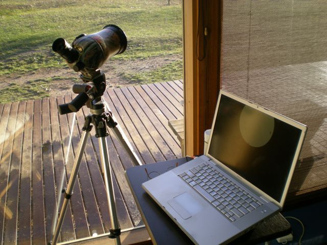
June 6, 2012. Observing the transit of Venus.


We were ready with a
home made N5 solar 
filter (from eBay) 
on our lil' 80mm
Maksutov Cassegrain
Spotting Scope 
(eBay again)


Expected C1 at 8:16 am.
The day dawned with
light cloud on the horizon 
but the sun rose above
the clouds into a clear
bright morning.
Weather: Perfect!


Used nice open source 
astronomy application 
Stellarium for real time 
tracking of approach 
of Venus to Sol.

The observation set up.


An early start to wash 
the window.
It was 8°C outside.
Amazing! 
Crude camera shot:
pointing a Nikon S200 
down the eye piece. 
That bump is Venus!


Followed the transit 
until noon then clouds
closed in. Didn't see 
the transit exit.


On a lighter side, 
here is what some 
of the worker bees 
would experience :)

Addendum:


Beautiful
image from 
JAXA's Hinode
space craft

Sunday, 4 March 2012

External aerial for EnviR transmitter

This project was inspired by a forum post on whirlpool.
The EnviR transmitter unit uses 433MHz wireless to transmit energy usage data packets to the display unit. The position of the transmitter unit is determined by the length of wire of the clamp, so is limited to about a metre from the measured wire. In my case the wireless signal was severely attenuated by the steel walls of the power room and the display unit showed poor signal quality. The clamp wire could not be extended to place the transmitter outside the room, as its length is tuned for the transmitter. The other option was replace the built in plastic aerial with an external aerial. I need about 1.5m cable to place the aerial outside the metal room. Adding an SMA connection on the transmitter allowed threading the aerial cable through a hole in the siding.
COMPONENTS
Two components were sourced from eBay:
433Mhz antenna 3dbi SMA Plug 
with Magnetic base with 1.5m cable

FME female to SMA female nut 
bulkhead RG174 jumper
Need only the SMA female nut and the RG174 cable. Discard FME connector.
Warning: Understand the difference between SMA and RP-SMA.

OPTIONAL COMPONENTS
90 degree MF SMA connector


INSTRUCTIONS
1. Open the transmitter back, one screw and remove batteries.
2. Pry open the case using a flat blade screw driver, starting at the bottom, by pushing in above the middle socket. Work left then right, then around the sides. The top will separate last, with a latch in the centre. 
3. Separate the case keeping the bottom edges close, be careful of the red and black power wires. Maybe you won't end up soldering them back on :(
4. Remove wire from plastic antenna. Note where the wire is soldered to wireless board.
5. Prep the SMA nut cable by cutting off the other end so it's about 100mm long and strip the outer insulation at least 25mm. Unbraid the shield and roll it into a wire. The core signal wire is cut about 16mm length and 8mm stripped of insulation, leaving 8mm insulation. Tin both wires lightly. The shield wire is tinned from the end until 5mm before the insulation. Don't tin further as it needs to bend and best not melt the insulation. Inspect and trim any straggler strands.
6. Test fit the SMA nut into the case before soldering. Enlarge the aerial hole in the case a little bit with a small round file or scrape with a knife. Test fitting the nut a few times requires closing up and prying open the case each time. With care the power cables won't snag, pinch or break.
7. Remove main board, 4 screws. The battery case is attached and care with the power cables is again required.

8. Notice there are many tiny holes in the main board which connect to the ground plane. There is one hole on the main board close by the signal connection on the wireless board. Drill that hole open with a 2mm drill and scratch away a bit of coating on the back to get fresh copper trace for soldering the shield.
9. Unsolder the original aerial wire and solder the new signal wire through the board, clip off extra length. Solder the shield wire into ground plane, soldering at back of main board, clip off extra length.
10. Replace main board into case, 4 screws. Final fit SMA nut and route cable to the top of case.
11. I used hot glue to fix the SMA nut to the case so it resists turning and used a tie plus hot glue to immobilise the soldered end of cable.
12. Assemble transmitter and tighten SMA nut with lock washer.
RESULTS
Preliminary:  The 14.1cm aerial with 1.5m cable has not yet arrived. Tested with a 3G aerial (34cm long is wrong for 433MHz) with 3m cable connected to transmitter.

The result: Absolutely fabulous, despite the mismatched aerial.
The important part was to get the Tx signal out of the metal enclosure. Received signal has no dropouts everywhere inside metal clad house, in places where no signal registered before.
CONCLUSION 
Success.

Tuesday, 5 April 2011

Hello World Of Blogging

print "Hello World" > blogosphere

(Always an easy starting point for a programmer...)

I've taken the plunge and started this blog, as what I say may be slightly more relevant than most :)


Now, just a quick word from our sponsor


Stay tuned for off-grid solar-powered living down-under (it's fabulous),
ruminations on climate collapse, (oil, schmoil, we are all gonna boil)
some rough and ready dharma (me) and more refined mindfulness (her)
and general geeking out in a sustainable solar powered lifestyle....